Article 2: Key Performance Factors for a 300A Industrial Thyristor
Industrial thyristors operate at the center of demanding power conversion systems. They regulate large amounts of electrical energy in equipment such as controlled rectifiers, induction and resistance furnaces, DC drives, electroplating power supplies, welding systems, battery chargers, and heavy-duty motor controllers. When a 300A device must be replaced, the engineer must identify the parameters that determine real-world performance rather than relying only on the current printed in a catalog.
The operating environment often combines high current, repeated switching, elevated temperature, and electrical transients. In melting furnace rectifiers gate trigger control 300A phase control thyristor applications, the semiconductor may be exposed to abrupt load changes and strong electromagnetic interference. Reliable operation depends on the interaction between the thyristor, its gate driver, the transformer, the load, the protective network, and the cooling assembly.
1. Current Capacity and Conduction Loss
The current rating of a thyristor is linked to specific thermal conditions. Manufacturers normally specify average on-state current at a defined case temperature and conduction waveform. If the actual cooling arrangement is less effective than the test condition, the device cannot safely carry the catalog current continuously.
Engineers should calculate conduction loss over the intended operating range. Thyristor voltage drop is not perfectly constant; it usually includes a threshold component and a current-dependent component. At high current, even a modest on-state voltage can produce several hundred watts of heat. This energy must move from the silicon junction through the package and into the heat sink without allowing the junction temperature to exceed its limit.
The importance of low on-state voltage drop for DC link rectification in drives 300A phase control thyristor selection becomes clear in continuous-duty systems. A reduction of only a few tenths of a volt can produce a meaningful decrease in heat generation at several hundred amperes. Lower conduction loss may allow a smaller cooling system, reduce fan loading, and improve the thermal margin of the complete drive cabinet.
Current capacity should also include overload performance. Short-duration overloads can occur during acceleration, process disturbances, transformer energization, or control faults. The surge current and I²t ratings indicate whether the thyristor can withstand these events while protective devices isolate the fault.
2. Blocking Voltage and Transient Protection
The replacement device must have adequate repetitive peak off-state and reverse voltage ratings. The selected voltage class should include margin for supply variation, commutation effects, switching transients, and transformer leakage inductance.
A thyristor with insufficient voltage margin may fail even when the measured line voltage appears normal. Short spikes can exceed the device limit for only microseconds, yet still damage the junction. RC snubber circuits, metal-oxide varistors, and properly coordinated fuses are therefore essential parts of the protection system.
When evaluating an Aluminium housing disc package for electro-plating rectifiers 300A phase control thyristor, technicians should inspect the busbar arrangement and snubber location. Long conductors can increase stray inductance, which raises transient voltage during current commutation. A mechanically compatible replacement should not force changes that lengthen critical current paths or weaken the original protection layout.
The rate of rise of off-state voltage, commonly expressed as dv/dt, also matters. A rapid voltage change can trigger a thyristor unintentionally if the device or circuit lacks sufficient immunity. This risk increases in electrically noisy environments and in systems where several switching devices share the same power structure.
3. Gate Drive Stability
The gate circuit determines when the thyristor begins conducting. A properly designed driver must deliver enough gate current for reliable turn-on under the lowest control voltage, lowest ambient temperature, and highest expected anode current rise condition.
In melting furnace rectifiers gate trigger control 300A phase control thyristor systems, the firing angle controls the energy delivered to the furnace load. Timing errors can produce uneven transformer loading, increased harmonic distortion, unstable heating, or excessive current in one phase. The replacement thyristor must therefore respond consistently to the existing trigger pulse.
Gate trigger current and voltage should be compared at the relevant temperature range. The pulse duration should be long enough to ensure that the anode current exceeds the latching current. Repetitive pulse trains may be used where load current is slow to build, particularly in inductive circuits.
Noise immunity is equally important. Gate and cathode conductors should be routed as a close pair, kept away from high-current busbars, and protected by shielding when necessary. Gate resistors, suppressors, and pulse transformers must be inspected for damage before a new thyristor is installed.
4. Package Construction and Cooling
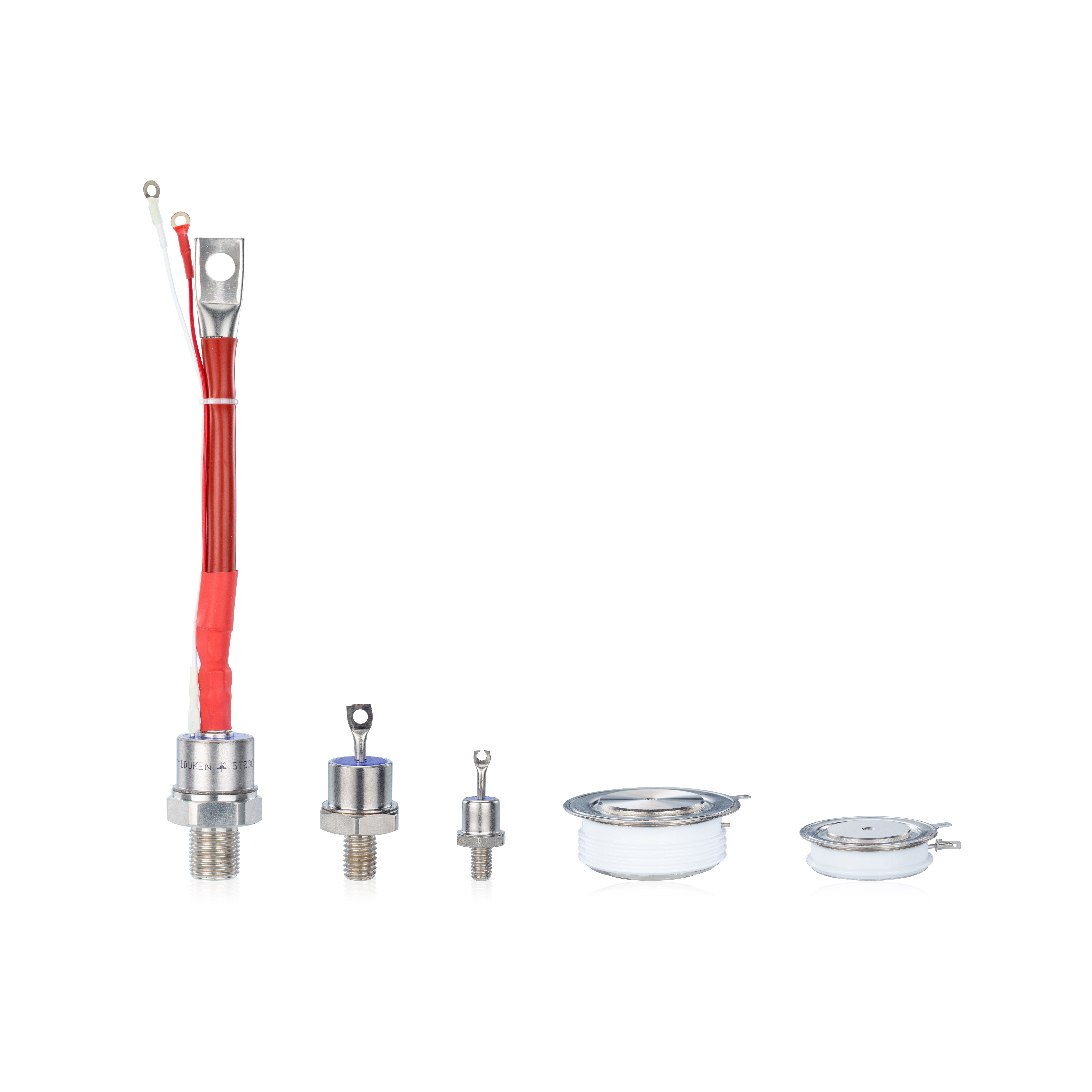
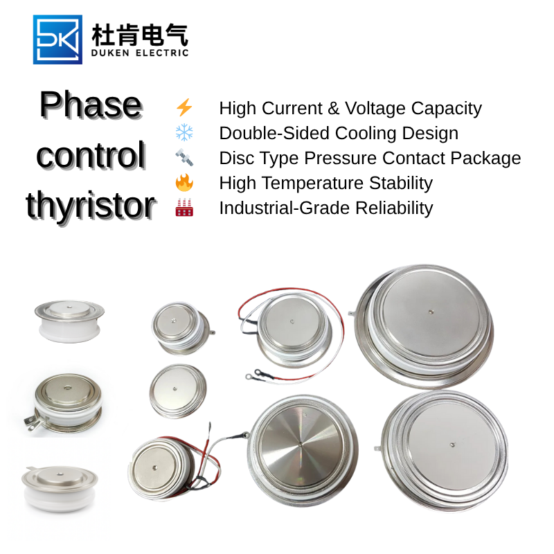
Disc thyristors are commonly used in high-current equipment because they provide large contact surfaces and efficient double-sided cooling. However, their performance depends heavily on correct mounting pressure and surface preparation.
An Aluminium housing disc package for electro-plating rectifiers 300A phase control thyristor must be installed between clean, flat cooling surfaces. The clamp should apply the manufacturer’s specified force uniformly across the device. Uneven pressure can create localized hot spots, increased contact resistance, and mechanical stress.
The heat sink must have sufficient thermal capacity for the calculated power loss. Cooling may be natural-air, forced-air, or water-based. In water-cooled rectifiers, flow rate, inlet temperature, water quality, and channel cleanliness influence the final junction temperature. A new thyristor cannot compensate for blocked cooling passages or failed fans.
Thermal cycling should also be considered. Equipment that repeatedly starts and stops produces expansion and contraction in the package, clamp, busbars, and heat sinks. A mechanically robust device and properly maintained clamping system reduce the risk of fatigue-related failure.
5. System-Level Replacement Validation
A successful replacement includes diagnostic work. The original failure should be investigated before power is reapplied. Common root causes include insufficient cooling, loose busbar connections, damaged snubbers, unequal phase currents, gate driver deterioration, output short circuits, and incorrect fuse coordination.
A device chosen for low on-state voltage drop for DC link rectification in drives 300A phase control thyristor service should be tested at different load levels. Engineers should compare DC output, phase current, heat-sink temperature, and voltage drop across each conducting device. Abnormal differences may indicate unequal firing or a mechanical contact problem.
For melting furnace rectifiers gate trigger control 300A phase control thyristor equipment, the test should cover startup, partial load, and full heating demand. For an Aluminium housing disc package for electro-plating rectifiers 300A phase control thyristor, extended operation at stable current is important because gradual temperature rise may reveal inadequate mounting or cooling.
The final selection should combine sufficient voltage margin, appropriate gate sensitivity, high surge capability, low conduction loss, strong thermal performance, and exact mechanical compatibility. When all these factors are verified, a 300A thyristor replacement can provide stable control, efficient power conversion, and a long operating life.