How to Choose a 300A Phase Control Thyristor: A Practical Selection Framework for Rectifiers and Industrial Power Conversion
How to Choose a 300A Phase Control Thyristor: A Practical Selection Framework for Rectifiers and Industrial Power Conversion
Author: Selina
1) Why “how to choose” is really about matching stress to margin
Selecting a 300A phase control thyristor is rarely about the number “300A.” That number is a starting point, not a guarantee. The real question is: under your waveform, your cooling method, your transient environment, and your commissioning practices, will the device keep enough margin to run reliably for years? A good selection process maps three stress categories—electrical, thermal, and mechanical—against the thyristor’s capability and your system’s controllability.
In industrial rectification and phase-angle control, failures often come from mismatches: a gate drive that is adequate at room temperature but marginal at high junction temperature; a snubber that is assumed rather than measured; or a thermal interface that performs well when clean but degrades quickly under dust and maintenance variation. The goal of this framework is to help you choose a device that remains stable when the cabinet is no longer new.
2) Step one: define the application family and its dominant risk
Different rectifier families stress the thyristor in different ways. Before choosing a device, classify your application by its dominant risks:
High-temperature, high-current rectifiers (furnaces and process heating): gate trigger stability, noise immunity, and coordinated protection are critical because the environment is harsh and switching disturbances are frequent.
Drive-related rectification (DC links, converters, regeneration systems): efficiency and thermal rise are often dominated by conduction loss, so forward characteristics and thermal path consistency become major selection factors.
Electro-plating rectifiers: reliability hinges on continuous duty, environmental exposure, and packaging integrity; mechanical interface and corrosion-related risks can be more significant than in clean industrial cabinets.
This is why specifications are often written in application language. For example, melting furnace rectifiers gate trigger control 300A phase control thyristor signals a noisy, high-stress environment where triggering robustness matters as much as current capability. In contrast, low on-state voltage drop for DC link rectification in drives 300A phase control thyristor highlights conduction loss as a primary driver of thermal performance and efficiency. And Aluminium housing disc package for electro-plating rectifiers 300A phase control thyristor points to packaging and mechanical protection as central to lifecycle reliability in corrosive or humid environments.
3) Step two: electrical selection—triggering, transients, and commutation realities
A phase control thyristor must block voltage reliably, turn on when commanded, and survive transients that are often created by the system itself. Electrical selection should include:
Gate trigger control and noise immunity:
Gate triggering is not simply “apply current, it turns on.” In real rectifier cabinets, gate lines can pick up interference, ground potential differences can shift references, and switching transients can inject noise into control electronics. For furnace systems, where busbars are large and power networks are noisy, the requirement behind melting furnace rectifiers gate trigger control 300A phase control thyristor is repeatable triggering under disturbance. You should design gate drive with headroom for temperature variation, and validate symmetrical triggering across conduction angles during commissioning.
dv/dt and transient protection:
Transients are influenced by wiring inductance, transformer behavior, contactor switching, and snubber placement. Even a robust thyristor can be overstressed if dv/dt is not controlled at the device terminals. Use snubbers and MOV coordination as engineering decisions, not generic add-ons. Where possible, verify with measurements under worst-case switching events—startup transitions, fault recovery, and maintenance switching.
Commutation and fault behavior:
In line-commutated systems, commutation overlap and current transfer behavior matter. If the system can experience line dips or sudden load changes, you need a device and protection plan that prevent repeated stress cycles.
4) Step three: thermal selection—what “300A” means in your cabinet
Thermal performance is the most common hidden cause of failure. A thyristor’s current rating assumes specific cooling and a stable thermal path. In practice, heat sink condition, airflow, mounting pressure, and interface material quality determine the true safe operating current.
Two practical approaches help:
Start with your worst ambient and degraded cooling: Assume filters partially clog, fans slow down, and fins accumulate dust. Build derating around the “bad but realistic” condition, not the ideal lab condition.
Prioritize conduction loss in DC link rectification: If your rectifier feeds a DC link in a drive, the thyristor’s conduction loss can dominate cabinet heating. That is why low on-state voltage drop for DC link rectification in drives 300A phase control thyristor selection is not a micro-optimization—it can be the difference between stable operation and chronic overtemperature alarms. Lower on-state drop generally reduces conduction losses, improving efficiency and thermal margin, but it must be considered alongside triggering requirements and voltage rating.
In continuous-duty rectifiers, thermal cycling also matters. If the load fluctuates, repeated heating and cooling can fatigue mechanical interfaces. Conservative derating and stable cooling reduce fatigue.
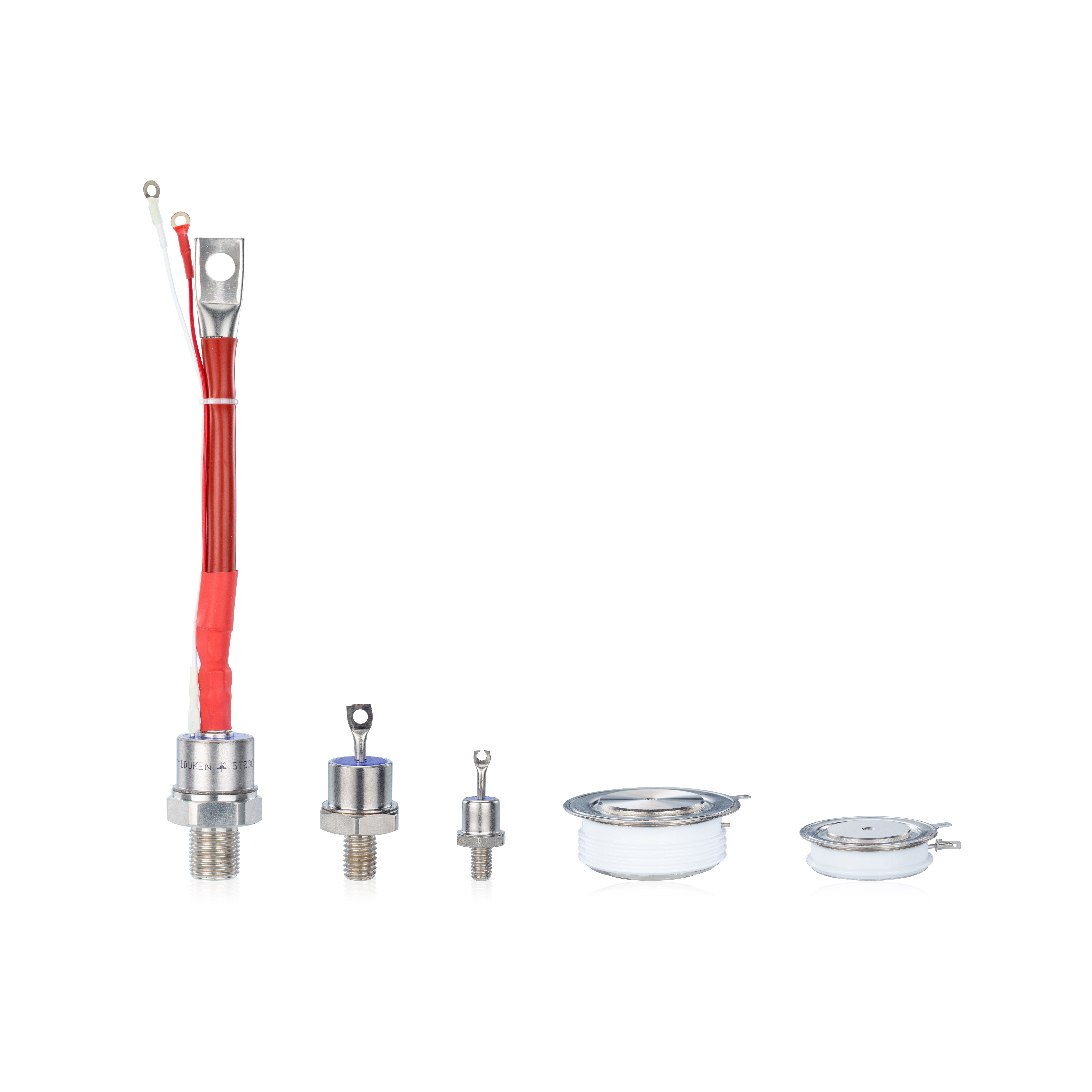
5) Step four: mechanical and packaging selection—disc packages and harsh environments
Packaging is not just “how it looks.” It determines creepage distances, sealing behavior, thermal interface style, and resistance to environmental exposure. Electro-plating rectifiers, in particular, often run in environments where humidity, chemical vapors, or conductive residues can accelerate corrosion and contamination.
That is why Aluminium housing disc package for electro-plating rectifiers 300A phase control thyristor appears in procurement language: it signals a preference for a mechanically protective housing and a disc-style package approach that supports consistent thermal contact and robust mounting. In these environments, selecting the right package can prevent issues that are not visible in electrical tests—surface contamination leading to leakage, mechanical looseness causing hot spots, or corrosion affecting contacts.
When choosing packaging, confirm:
Mounting method and clamp force consistency
Surface preparation and interface material practice
Environmental sealing expectations and cabinet cleanliness strategy
Service repeatability: can technicians replace devices without introducing variability?
6) Closing: a “good choice” is one you can validate and maintain
The best 300A thyristor choice is the one that remains predictable across commissioning, production scale-up, and years of maintenance. Use the application language as a guide: melting furnace rectifiers gate trigger control 300A phase control thyristor emphasizes triggering robustness; low on-state voltage drop for DC link rectification in drives 300A phase control thyristor emphasizes efficiency and thermal margin; and Aluminium housing disc package for electro-plating rectifiers 300A phase control thyristor emphasizes packaging resilience and serviceability.
If you build your selection around these stress categories—and validate with commissioning checks and trend monitoring—you’ll choose a device that doesn’t just “work,” but keeps working.