Identifying Root Causes of 500A Phase Control Thyristor Failures
Introduction
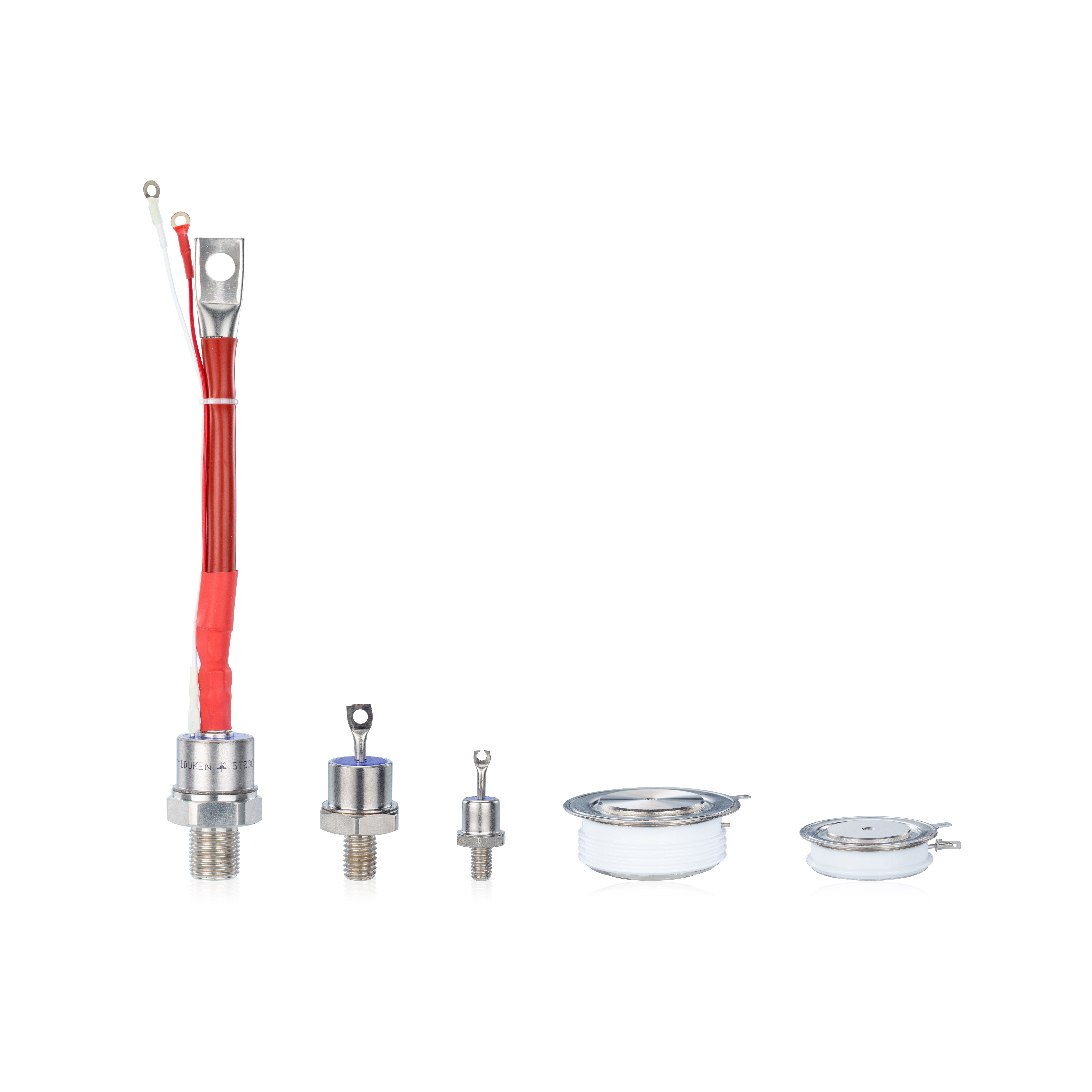
The 500A phase control thyristor is a critical component in industrial systems requiring high power handling and precision control. Despite their robust design, these thyristors can fail due to electrical, thermal, or mechanical stress. Understanding the root causes of these failures is key to improving system reliability and ensuring long-term performance.
Overheating and Thermal Breakdown
One of the most common failure points for thyristors is overheating. Though built with high thermal stability, these components rely on effective thermal management. If heat is not efficiently removed through proper heatsinks or thermal pads, the thyristor’s core temperature may exceed safe limits.
This becomes especially critical under high surge current rating events, where sudden loads introduce excessive heat in milliseconds. The 500A phase control thyristor is engineered to absorb high surges, but exceeding its rating repeatedly will degrade internal materials, leading to breakdown or performance drift.
Engineers must monitor case and junction temperatures using thermal sensors and ensure that heatsinks are not undersized or obstructed by dust buildup.
Gate Trigger Anomalies and dv/dt Effects
Unexpected turn-on behavior can be linked to poor gate signal quality or excessive dv/dt conditions. A key strength of these thyristors is their high dv/dt immunity, but even this has limits. If the circuit's snubber network is poorly designed or omitted, voltage transients can lead to unintended triggering.
Also, signal integrity issues in the gate circuit may lead to misfiring or delayed conduction. System designers must ensure clean gate trigger pulses, with appropriate voltage and rise time, especially during cold starts or when the system operates near its extended temperature range (–40°C to +85 °C).
Proper shielding, trace design, and snubber circuits are essential to preserving dv/dt integrity.
Leakage Current Indicators and Aging Effects
Low leakage current is an expected trait of new thyristors. However, when internal degradation occurs—due to overvoltage, contamination, or moisture ingress—leakage tends to rise. This subtle change often precedes catastrophic failure, making it an important diagnostic metric.
Over time, prolonged high-temperature exposure can exceed the high junction temperature tolerance, weakening the silicon junction and altering breakdown voltages. Engineers should periodically measure reverse leakage current and compare it to baseline values from commissioning.
This proactive measure helps in identifying aging thyristors before they fail during operation.
Application Stress and Incorrect Sizing
Another common but overlooked cause of failure is using a thyristor in a circuit that exceeds or closely approaches its rated limits. While the 500A phase control thyristor is designed for tough environments, consistent operation near thermal or current thresholds accelerates wear.
Engineers should not only verify peak ratings but also confirm safe operating areas under transient and repetitive cycles. The extended temperature range (–40°C to +85 °C) may give a false sense of security—designers must consider ambient heat and enclosure buildup as well.
Use of simulation tools and real-time monitoring ensures proper alignment of system load profiles with thyristor capability.