Optimizing Thyristor Module Integration in Modern UPS Architectures
1. Trends in UPS Design and Their Impact on Power Modules
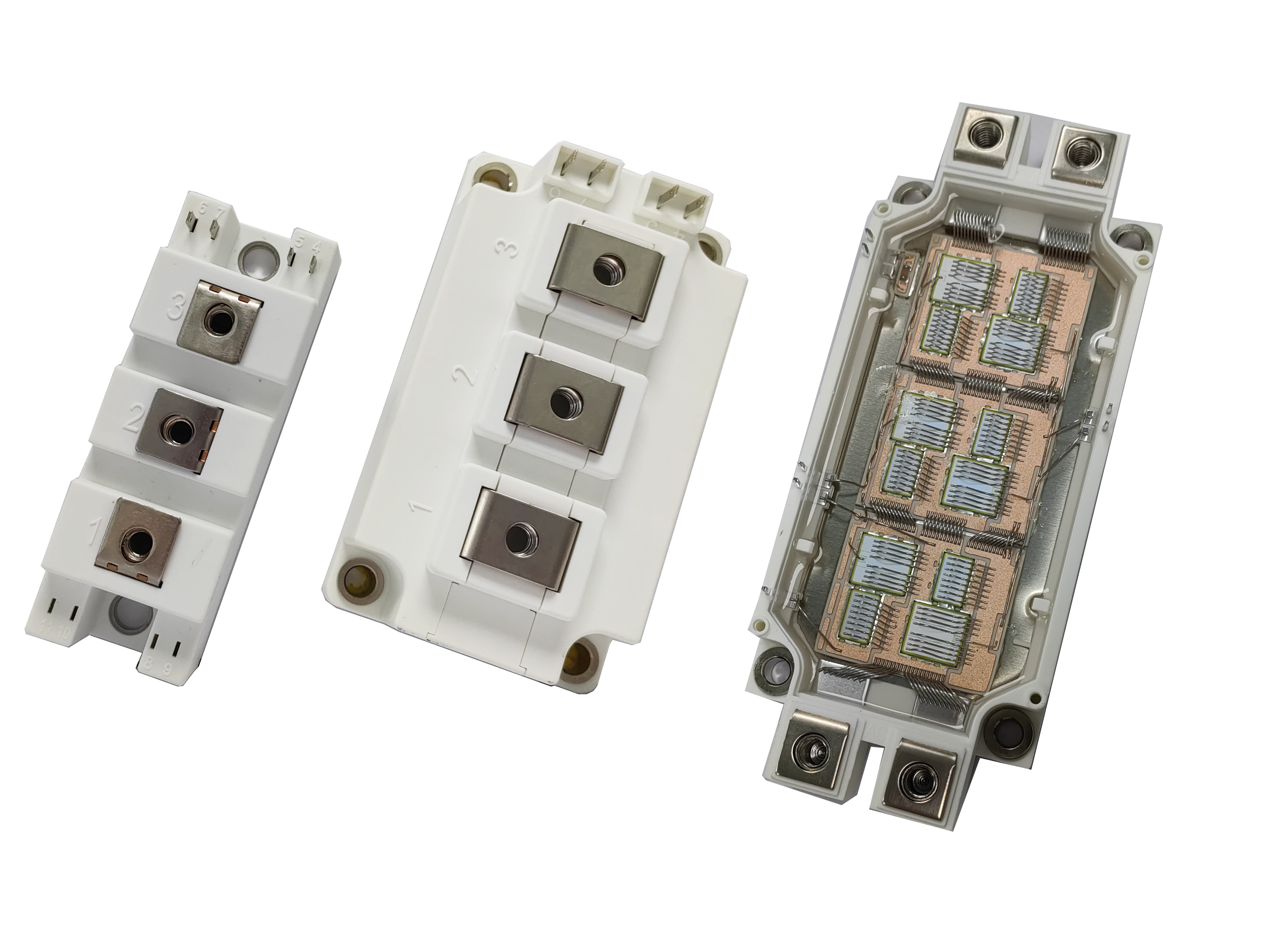
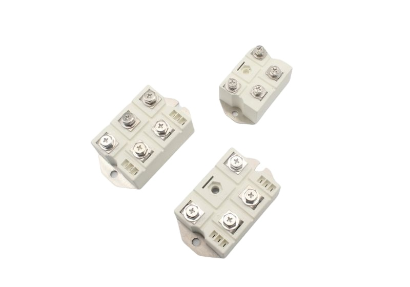
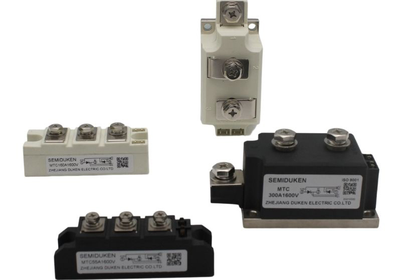
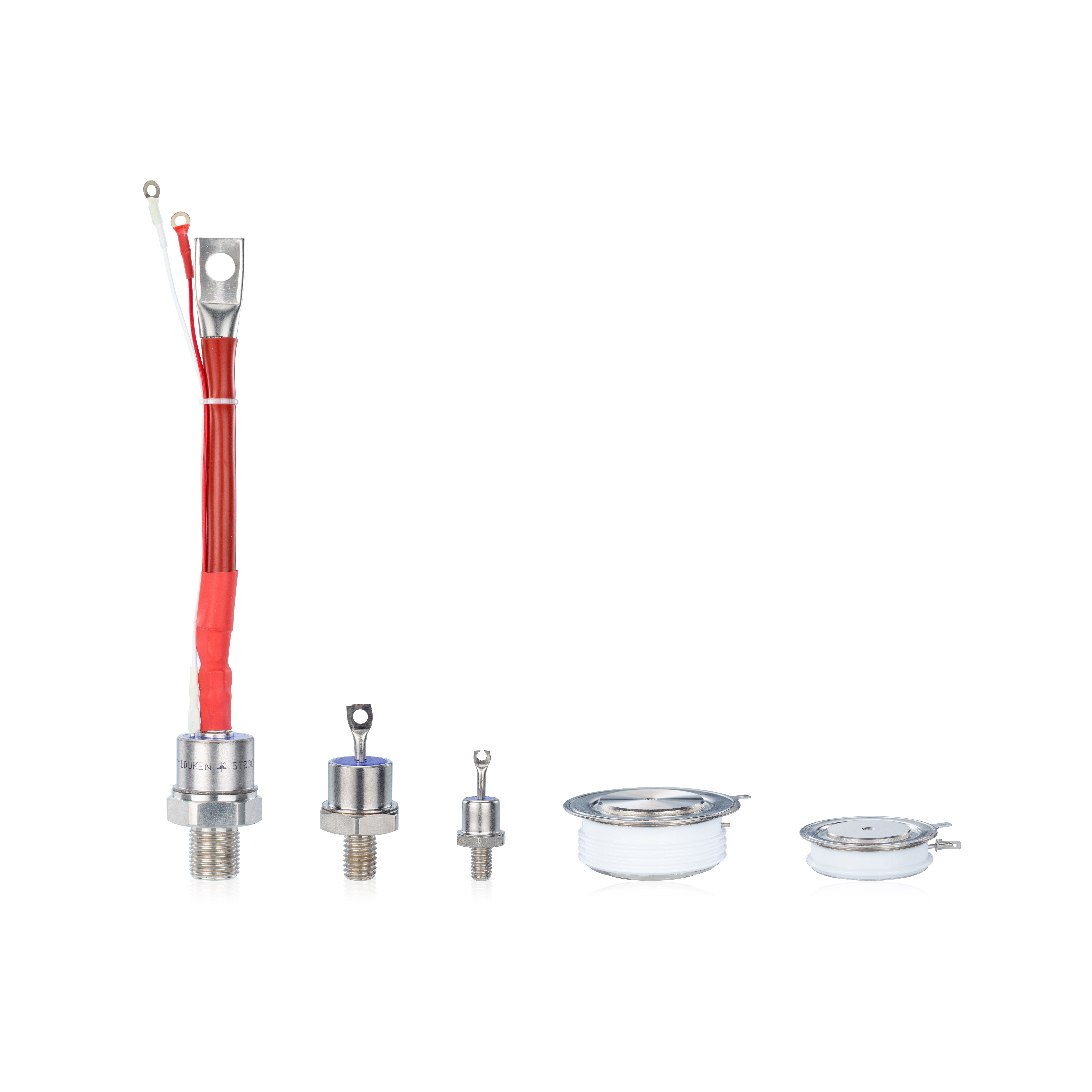
As UPS technology evolves, so do the demands placed on components such as thyristor modules. Higher efficiency, compact layout, and faster switching require new thinking in module selection and implementation. In this context, solutions like the low gate-trigger screw-terminal surge-protection 106A thyristor module for ups systems, anti-parallel OEM certified 106A thyristor module for ups systems, and phase-control hard-soldered-joints low forward-voltage 106A thyristor module for ups systems must be carefully integrated to match system dynamics.
2. Design Considerations for Reliable Integration
2.1 Gate signal conditioning
As switching frequency increases, the integrity of the gate pulse becomes critical. The low gate-trigger screw-terminal surge-protection 106A thyristor module for ups systems benefits from clean, short rise-time gate pulses to ensure robust conduction. The anti-parallel OEM certified 106A thyristor module for ups systems must have matching driver topology on both sides to maintain symmetry. Phase-control hard-soldered-joints low forward-voltage 106A thyristor module for ups systems needs extra care in isolation to prevent noise-induced misfiring.
2.2 PCB layout and parasitic effects
Compact UPS designs can inadvertently introduce parasitics. The low gate-trigger screw-terminal surge-protection 106A thyristor module for ups systems should be placed to minimize loop area for current paths. In anti-parallel OEM certified 106A thyristor module for ups systems, ensure identical routing for each module path. The phase-control hard-soldered-joints low forward-voltage 106A thyristor module for ups systems can be affected by insufficient copper plane distribution—leading to uneven current sharing.
3. Performance Testing During Prototyping
3.1 Pulse load testing
Simulating surge conditions validates thermal and electrical robustness. The low gate-trigger screw-terminal surge-protection 106A thyristor module for ups systems should handle short bursts without breakdown. Anti-parallel OEM certified 106A thyristor module for ups systems should demonstrate consistent behavior across both legs during pulse transitions. The phase-control hard-soldered-joints low forward-voltage 106A thyristor module for ups systems should exhibit minimal overshoot and stable conduction under repeated pulsing.
3.2 Temperature chamber cycling
Modules exposed to controlled thermal cycles can reveal long-term weaknesses. The low gate-trigger screw-terminal surge-protection 106A thyristor module for ups systems should show minimal parameter drift. Anti-parallel OEM certified 106A thyristor module for ups systems should maintain conduction symmetry at extreme temperatures. The phase-control hard-soldered-joints low forward-voltage 106A thyristor module for ups systems must pass solder joint reliability under expansion stress.
4. Installation Tips for Field Technicians
4.1 Clean connections and torque control
Always clean contacts before mounting the low gate-trigger screw-terminal surge-protection 106A thyristor module for ups systems, and torque evenly to avoid hotspots. Use heat pads or thermal paste on anti-parallel OEM certified 106A thyristor module for ups systems to ensure efficient dissipation. Avoid mechanical flex on the phase-control hard-soldered-joints low forward-voltage 106A thyristor module for ups systems, as it can cause solder fracture over time.
4.2 Grounding and shielding
Provide strong, low-impedance ground return paths for all thyristor modules. Especially for phase-control hard-soldered-joints low forward-voltage 106A thyristor module for ups systems, proper grounding helps avoid EMI-related faults.