Driver Coordination Strategies for 106A Thyristor Modules in UPS Systems
1. Overview: Driver Circuits for Modern Thyristor Modules
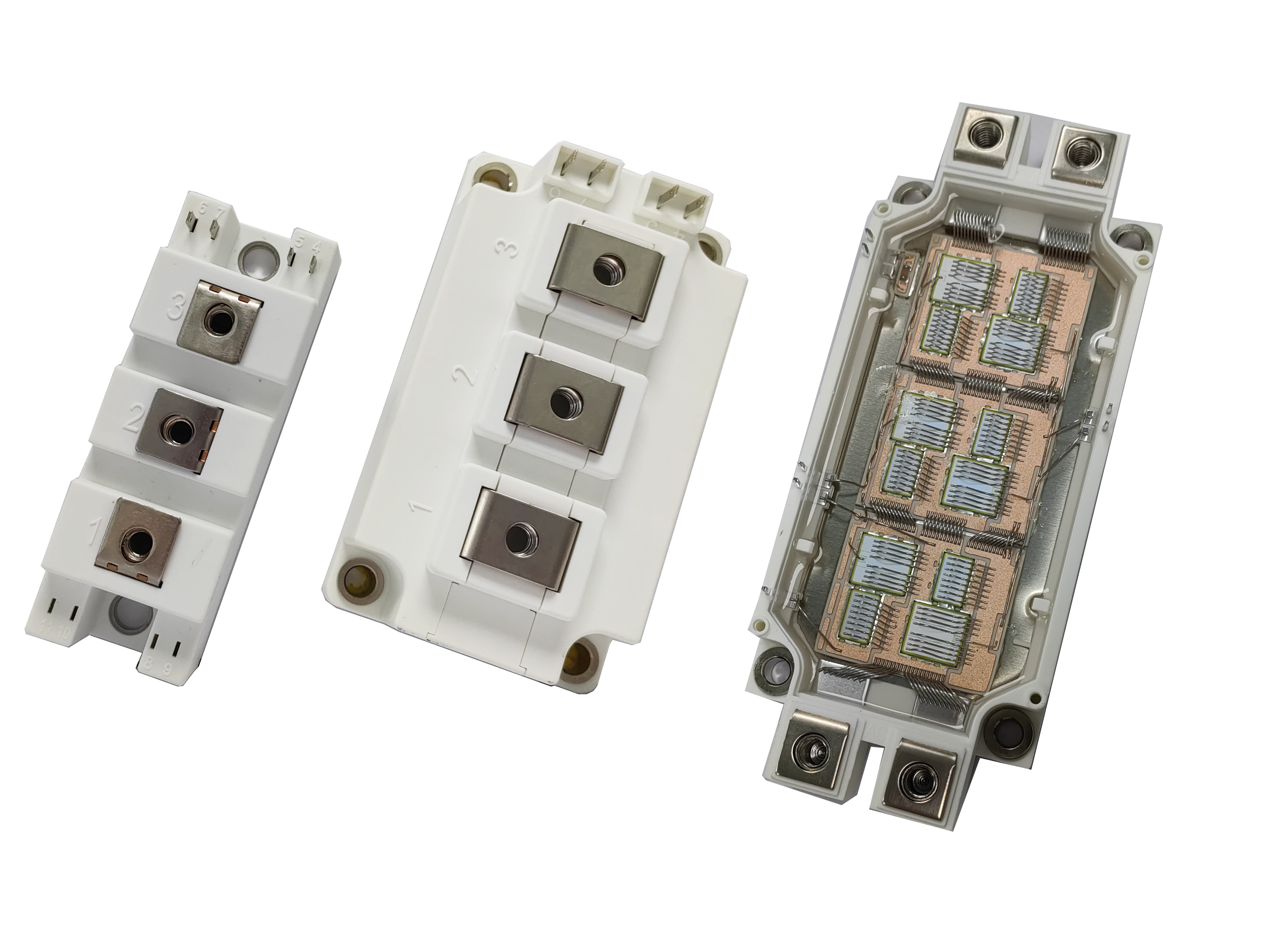
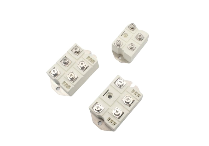
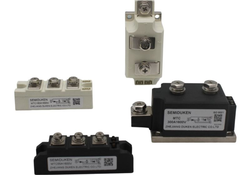
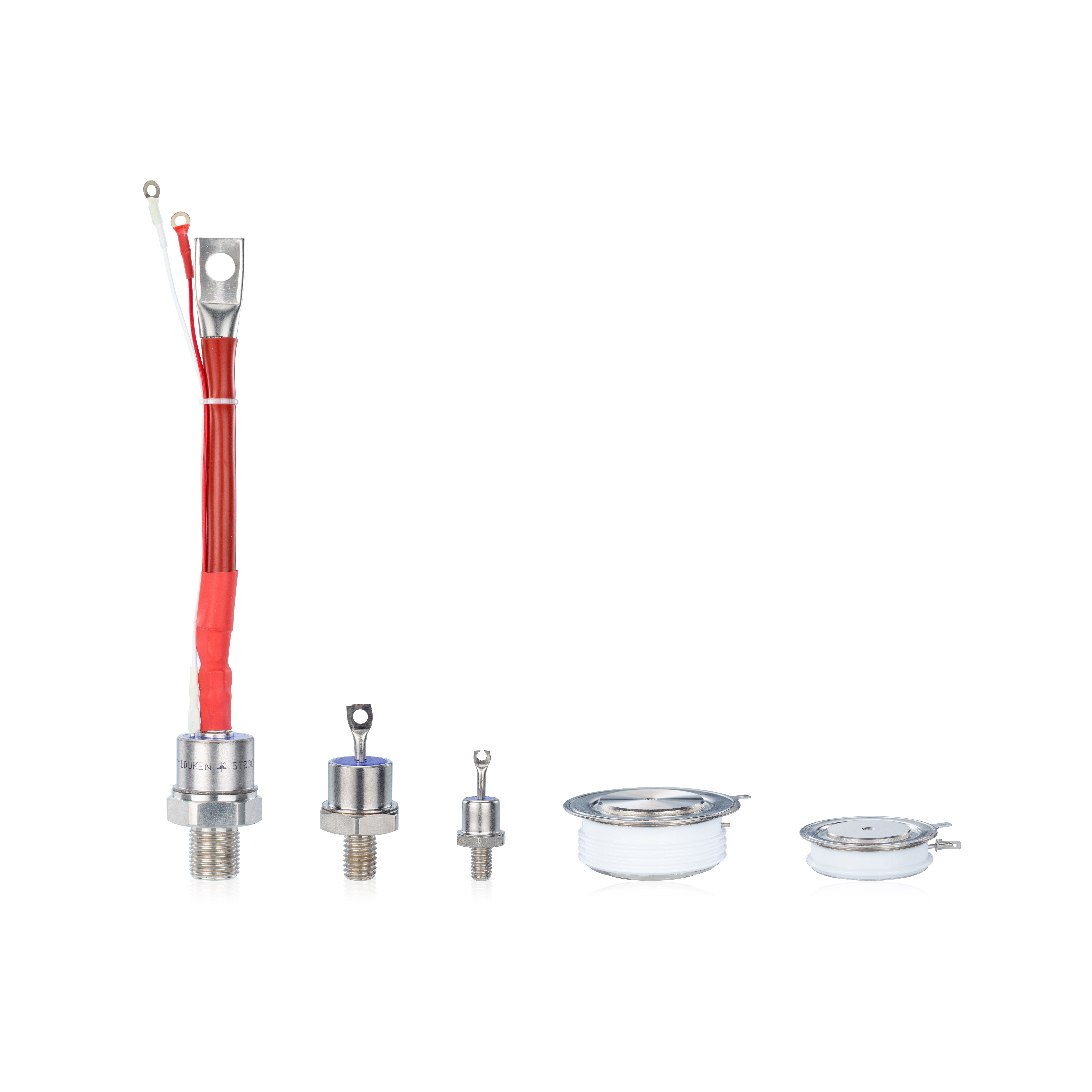
Selecting the right driver circuits and controllers is crucial for high-reliability UPS systems. These circuits must match the electrical, thermal, and mechanical attributes of the thyristor modules. In this article, we explore driver and controller strategies for modules including aluminum‑oxide‑baseplate compact UL‑recognized 106A thyristor module for ups systems, phase‑angle‑control surge‑protection compact 106A thyristor module for ups systems, and hard‑soldered‑joints screw‑mount panel‑mount 106A thyristor module for ups systems.
2. Drivers for Aluminum‑Oxide Baseplate Modules
2.1 Electrical Matching and Insulation
The aluminum‑oxide‑baseplate compact UL‑recognized 106A thyristor module for ups systems benefits from its baseplate’s thermal conductivity and insulation. But that also means the driver circuit must avoid over‑stressing the base via dv/dt or overshoot. The driver should have slew control, gate current limiting, and soft gating to match the module’s tolerance.
Using a controller that dynamically adjusts gate current based on temperature helps when working with aluminum‑oxide‑baseplate compact UL‑recognized 106A thyristor module for ups systems, because the module’s thermal paths can vary depending on mounting. Also, isolated drivers with reinforced insulation help maintain safety margins when paired with aluminum‑oxide‑baseplate compact UL‑recognized 106A thyristor module for ups systems in compact UPS applications.
2.2 Recommended Driver Topologies
A suitable approach is to use a dedicated isolated gate driver IC with programmable rise/fall control, along with an MCU or FPGA that orchestrates gating, health monitoring, and fault logic. The controller should support features like dead time, adjustable gate drive strength, and adaptive derating when the module is under stress — especially useful for the aluminum‑oxide‑baseplate compact UL‑recognized 106A thyristor module for ups systems.
3. Drivers for Phase‑Angle and Surge‑Protection Modules
3.1 Precision Timing & Surge Resilience
Modules labeled phase‑angle‑control surge‑protection compact 106A thyristor module for ups systems are designed for controlled conduction (phase-angle modulation) and built-in surge tolerance. The driver must support fine timing resolution, synchronized triggering, and real-time protection decisions.
A controller for phase‑angle‑control surge‑protection compact 106A thyristor module for ups systems often uses DSP/FPGA to compute gating angles, detect system faults, and adjust gate pulses dynamically. This allows load regulation while protecting against overcurrent or voltage spikes.
When designing for phase‑angle‑control surge‑protection compact 106A thyristor module for ups systems, the driver should include adaptive gate drive strength, active clamp circuits, and current sensing feedback loops.
3.2 Surge Protection in the Driver Circuit
To complement the module, the driver must incorporate desaturation detection, overvoltage clamps, and carefully matched snubber networks. The integration between controller and driver ensures real-time reaction to surge events when using phase‑angle‑control surge‑protection compact 106A thyristor module for ups systems.
4. Drivers for Hard‑Soldered, Panel‑Mount Modules
4.1 Mechanical Rigidity and Electrical Integrity
The hard‑soldered‑joints screw‑mount panel‑mount 106A thyristor module for ups systems presents robust mechanical mounting and tighter thermal contact. But that increases the need for low-inductance gating and careful grounding in the driver design.
Drivers interfacing with hard‑soldered‑joints screw‑mount panel‑mount 106A thyristor module for ups systems should use compact, tight gate loops and avoid long traces. The controller must manage gate currents precisely because the mechanical rigidity allows less margin for parasitic effects.
Also, when using a hard‑soldered‑joints screw‑mount panel‑mount 106A thyristor module for ups systems, the driver board’s placement relative to the module is crucial. Grounding layout must be optimized to prevent mis-trigger or noise.
4.2 Suggested Driver Implementation
Use multi-stage isolation (e.g., optocoupler + transformer + capacitive barrier) and reinforced driver circuits that support adjustable gate strength. The controller should support skew compensation, dynamic gate ratios, and fault detection tailored to the mechanical context of hard‑soldered‑joints screw‑mount panel‑mount 106A thyristor module for ups systems.
5. Design Guidelines and Implementation Best Practices
5.1 Mapping Driver Features to Module Requirements
For aluminum‑oxide‑baseplate compact UL‑recognized 106A thyristor module for ups systems: emphasize insulation, controlled dv/dt, and thermal-aware gating
For phase‑angle‑control surge‑protection compact 106A thyristor module for ups systems: focus on timing precision, adaptive gating, and protection logic
For hard‑soldered‑joints screw‑mount panel‑mount 106A thyristor module for ups systems: prioritize low inductance layout, grounding integrity, and mechanical-aware design
5.2 Shared Configuration Tips
Use selectable gate resistor networks for tuning switching behavior
Embed desaturation, overvoltage, and overtemperature protection
Provide temperature feedback and dynamic derating
Integrate controller logic (microcontroller, FPGA, or DSP) for holistic coordination
5.3 System-Level Integration
Modern UPS systems often host driver and controller logic in centralized DSP or FPGA modules. These generate phase commands, monitor health signals, and coordinate gating signals to driver boards. Effective system integration ensures consistent operation across module variant types.