Replacement Procedures for Thyristor Modules in UPS Systems
1. Thermal & Mechanical Verification After Replacement
1.1 Thermal coupling and heat flow checking
Once the replacement module is installed, it is critical to verify that thermal coupling is optimal. Use an infrared camera or thermal probe to map junction-to-heatsink temperature gradients. Any localized hotspots may indicate poor mounting or insufficient thermal interface.
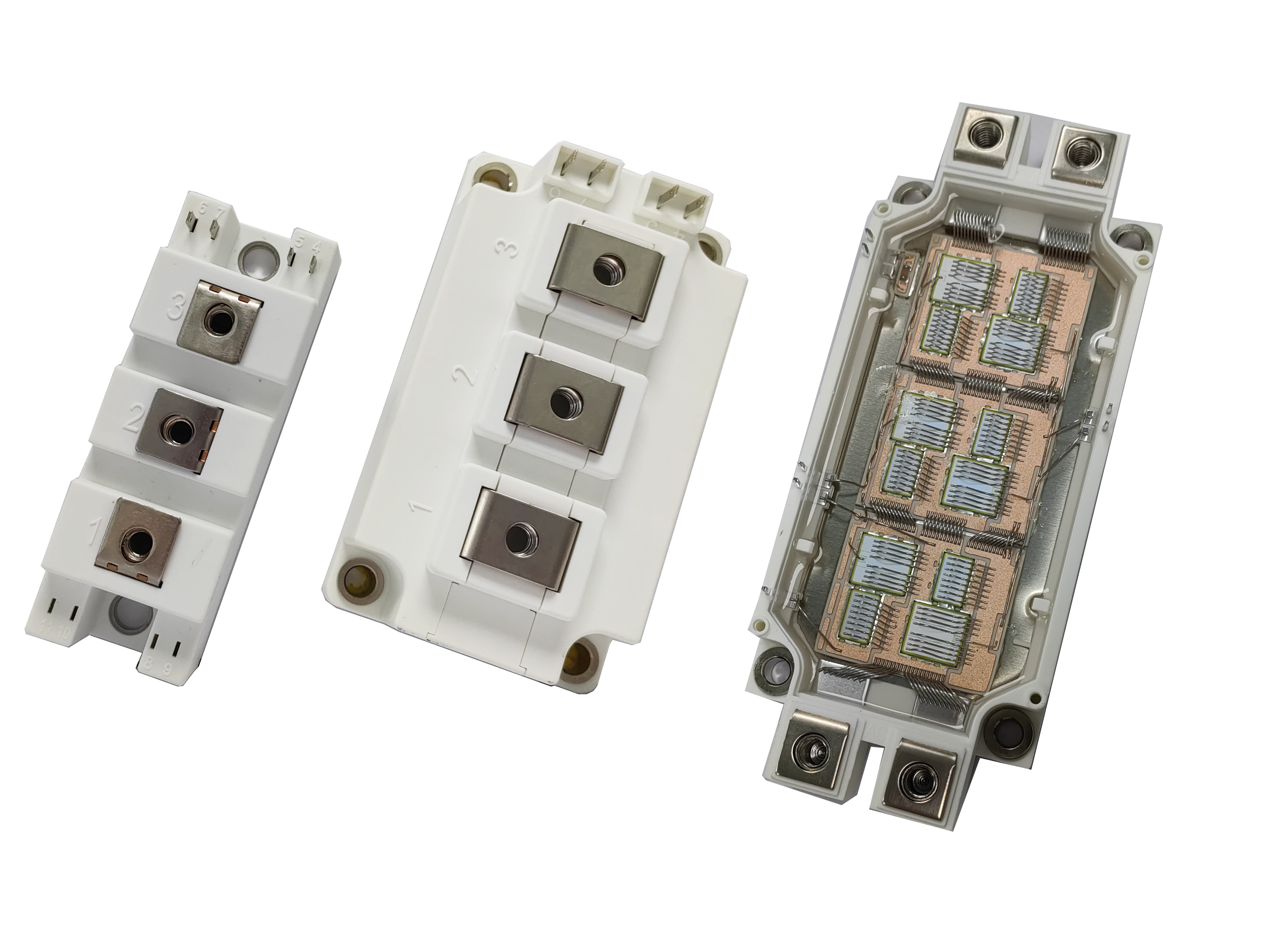
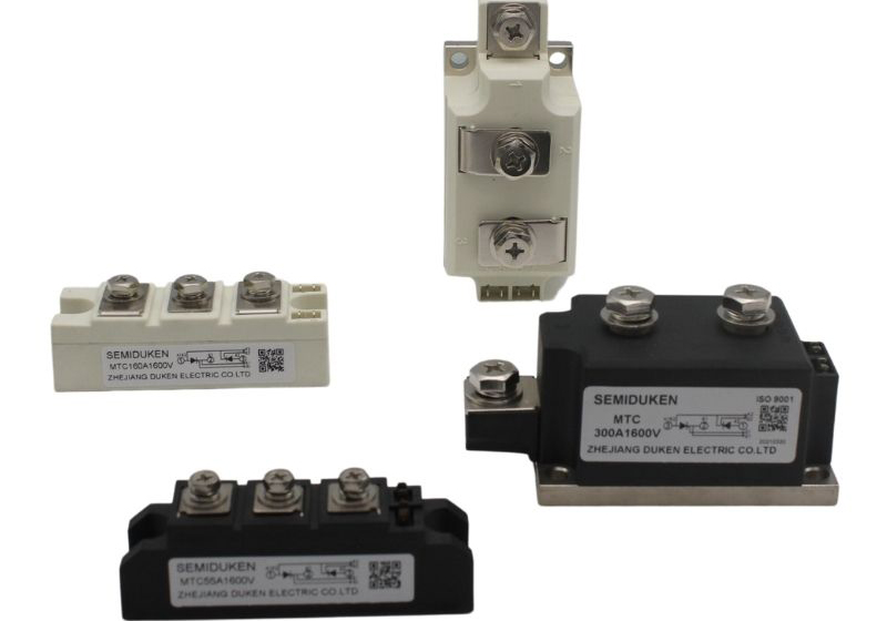
For a 14500A high frequency anodizing High surge current low on‑state voltage industrial phase control dual thyristor module, check for uniform temperature across the base under load, as uneven heating may degrade ceramic or solder joints.
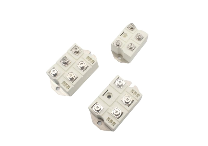
If using a compact package desalination energy storage High surge current low on‑state voltage industrial phase control dual thyristor module, confirm that compact cooling channels or micro‑fins are not starved of airflow, which might otherwise create thermal bottlenecks.
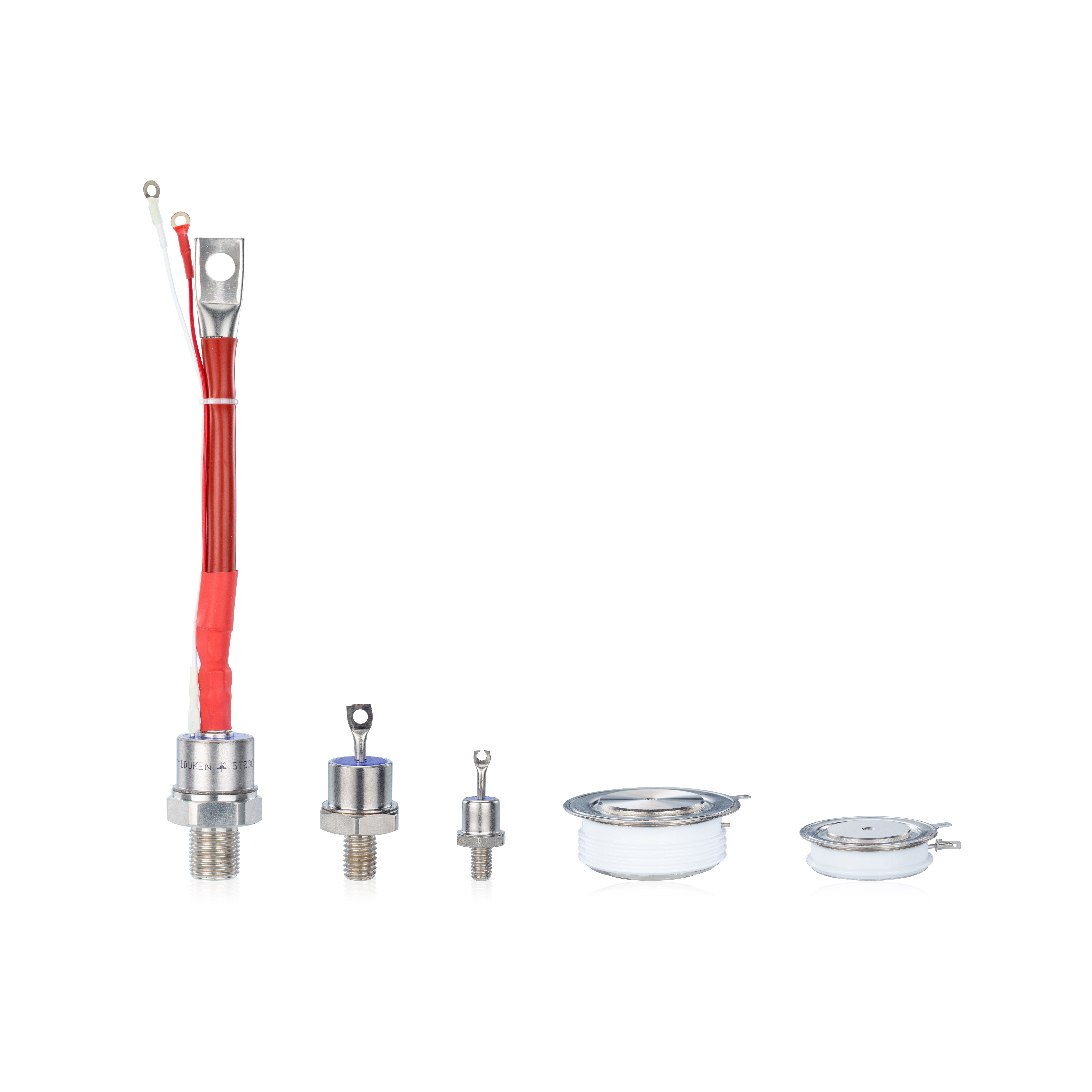
In installations with HVDC ceramic base plasma cutter High surge current low on‑state voltage industrial phase control dual thyristor module, ensure that thermal drift under pulsed high-voltage conditions remains within acceptable limits and does not lead to base cracking.
1.2 Mechanical stress and vibration checks
After module replacement, verify that mounting hardware remains tight, and re-confirm torque values under thermal load. Thermal expansion cycles may cause loosening over time.
Perform mechanical vibration or shock tests (if permitted) to check for module stability, especially in systems subject to field vibration (e.g. generator rooms).
Inspect ceramic bases, leads, and busbars for signs of bending or strain, particularly for the HVDC ceramic base plasma cutter High surge current low on‑state voltage industrial phase control dual thyristor module, where rigid structures may not accommodate expansion without stress.
2. Gate Drive & Signal Integrity Verification
2.1 Gate waveform integrity under full load
Record gate-to-cathode voltage waveforms using an oscilloscope under actual load conditions, not just no-load. Check rise/fall times, overshoot, ringing, or abnormal distortions.
For the 14500A high frequency anodizing High surge current low on‑state voltage industrial phase control dual thyristor module, the high frequency switching environment demands clean gate edges and minimal ringing to avoid misfiring.
In systems with compact package desalination energy storage High surge current low on‑state voltage industrial phase control dual thyristor module, ensure that compact wiring and tight packaging do not degrade signal integrity.
When using HVDC ceramic base plasma cutter High surge current low on‑state voltage industrial phase control dual thyristor module, confirm that the high-voltage environment does not induce coupling or interference on gate leads.
2.2 Synchronization, delay calibration, and trimming
Check that all modules (especially in multi‑leg UPS topologies) are triggered synchronously. Any skew in gate timing can lead to uneven current sharing or stress.
Perform calibration of trigger delay and gate drive amplitude under temperature and load stress. Adjust gate resistors or compensation if needed.
Verify that the module’s gate threshold (I_GT) is consistent with manufacturer spec and remains stable across temperature and cycle count.
3. Commissioning Load Ramp & Stress Testing
3.1 Low‑power initial test & safety envelope verification
Before applying full load, run initial tests at low current to validate basic conduction, gate behavior, and absence of leakage. This step helps catch wiring mistakes or insulation faults without damaging modules.
Use incremental current steps while continuously monitoring module voltages, temperatures, and waveforms.
3.2 Surge, transient, and fault-response validation
Apply controlled surges or transient events (within rated envelope) to verify that the replacement module responds safely and reliably.
Specifically test for modules like 14500A high frequency anodizing High surge current low on‑state voltage industrial phase control dual thyristor module under expected surge waveforms, and ensure no misfire or damage.
For compact package desalination energy storage High surge current low on‑state voltage industrial phase control dual thyristor module, simulate rapid charge/discharge pulses to ensure module integrity under dynamic conditions.
For HVDC ceramic base plasma cutter High surge current low on‑state voltage industrial phase control dual thyristor module, test pulsed HV loads to ensure the ceramic base and junction withstand the stress without creeping conduction.
3.3 Long-term burn‑in and stability monitoring
After passing surge tests, allow the system to operate under nominal load for an extended burn-in period (hours to days) to verify stability. Monitor metrics such as on-state voltage drift, leakage current, temperature rise, and gate behavior trends.
Log these metrics and compare to expected baselines to detect latent defects early. If drift or anomalies appear, pause further operation and re-evaluate.