How to Choose a 1400A Phase Control Thyristor for High-Power Conversion Systems
Selecting a 1400A phase control thyristor is not simply a matter of matching the current rating on a nameplate. In high-power rectifiers, industrial soft starters, DC drives, controlled heating systems, excitation equipment, electrolysis power supplies, and grid-connected conversion systems, the thyristor becomes a core switching device that must handle repetitive electrical stress, transient overloads, thermal cycling, mechanical pressure, and long operating hours. A well-selected device improves efficiency, stability, and service life, while a poorly selected one can lead to overheating, nuisance shutdowns, voltage imbalance, or catastrophic failure.
For engineers and purchasing teams, the choice usually begins with voltage class, current capability, surge tolerance, leakage behavior, package style, and thermal performance. A device such as the datasheet KP1400A‑6500V low leakage current 1400A phase control thyristor is typically evaluated in applications where high blocking voltage, reliable current control, and stable operation under demanding industrial conditions are required. The key is to connect the values on the datasheet with the real electrical and thermal environment of the equipment.
1. Start with the operating voltage and safety margin
The voltage rating is one of the first parameters to review. In a controlled rectifier or AC power controller, the thyristor must block voltage when it is in the off state. The selected voltage rating should not only cover the normal line voltage, but also allow enough margin for switching transients, grid fluctuation, insulation coordination, and possible overvoltage caused by inductive loads.
For medium-voltage and high-power systems, a 6500V class component can provide a useful design margin. When reviewing the datasheet KP1400A‑6500V low leakage current 1400A phase control thyristor, engineers should compare repetitive peak off-state voltage, repetitive peak reverse voltage, non-repetitive voltage limits, and recommended derating. It is common practice to avoid operating continuously near the absolute maximum rating because real installations experience voltage spikes, harmonic distortion, and uneven sharing in series-connected designs.
Voltage selection also affects snubber design. A thyristor with good voltage capability still requires proper RC snubbers, surge arresters, and layout control to prevent excessive dv/dt. The device rating and the protection network should be treated as a coordinated system, not as separate decisions.
2. Match current rating to real load conditions
The rated 1400A value must be interpreted carefully. Thyristor current ratings depend on waveform, conduction angle, cooling conditions, heatsink temperature, mounting force, and duty cycle. A device may be rated for a certain average current under specified case temperature, but the actual application may involve different pulse patterns, overload intervals, and ambient temperature.
When selecting a 1400A phase control thyristor, calculate RMS current, average current, peak repetitive current, and overload current. In phase control circuits, current is often non-sinusoidal. This means thermal losses can be higher than expected if only the average current is considered. The forward voltage drop also contributes to heat generation, so conduction loss should be estimated under the expected operating current.
For heavy industrial loads, the high surge current rating Aluminium housing disc package 1400A phase control thyristor is particularly valuable because many systems face inrush current, short overloads, transformer magnetizing current, or fault-clearing stress. Surge current capability helps determine whether the device can survive abnormal but predictable events before fuses, breakers, or electronic protection act.
3. Review leakage current and blocking stability
Low leakage current is important in high-voltage thyristors because excessive off-state leakage increases heat, reduces blocking reliability, and may indicate poor behavior at elevated temperature. In series stacks, leakage differences can also affect static voltage sharing between devices. A thyristor with controlled leakage characteristics helps improve predictable blocking performance.
The phrase datasheet KP1400A‑6500V low leakage current 1400A phase control thyristor should guide engineers to examine leakage at rated voltage and specified junction temperature. It is not enough to look at leakage at room temperature; leakage generally rises with temperature. In equipment that runs continuously, especially in sealed cabinets or hot industrial locations, leakage performance at high temperature matters more than ideal laboratory conditions.
Low leakage current also supports better standby efficiency and reduces the burden on voltage-sharing resistors. For high-voltage assemblies, consistent leakage values across batches can simplify design validation and improve long-term service confidence.
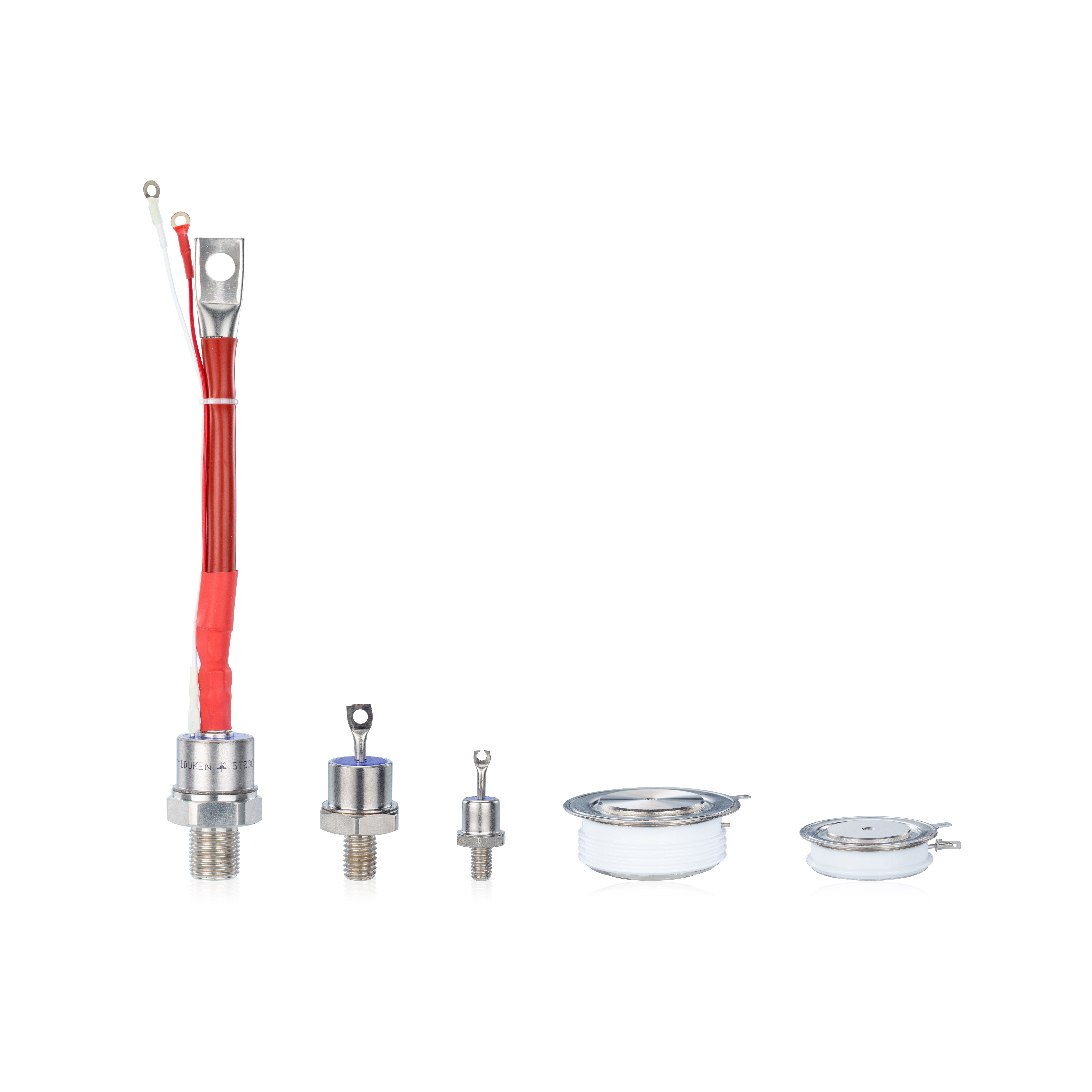
4. Consider surge rating, package design, and thermal path
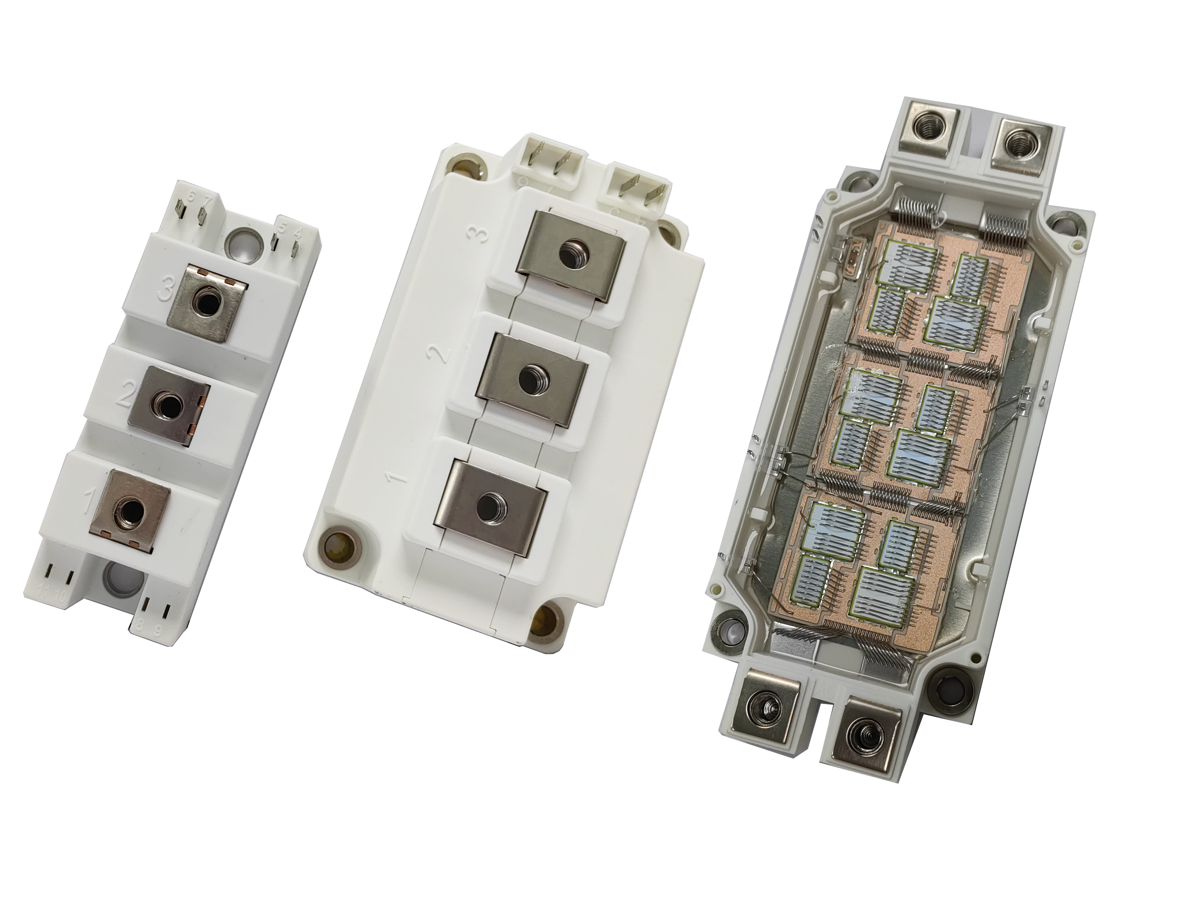
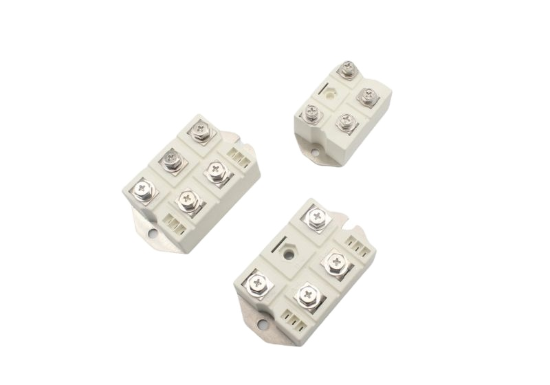
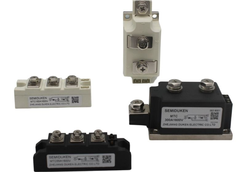
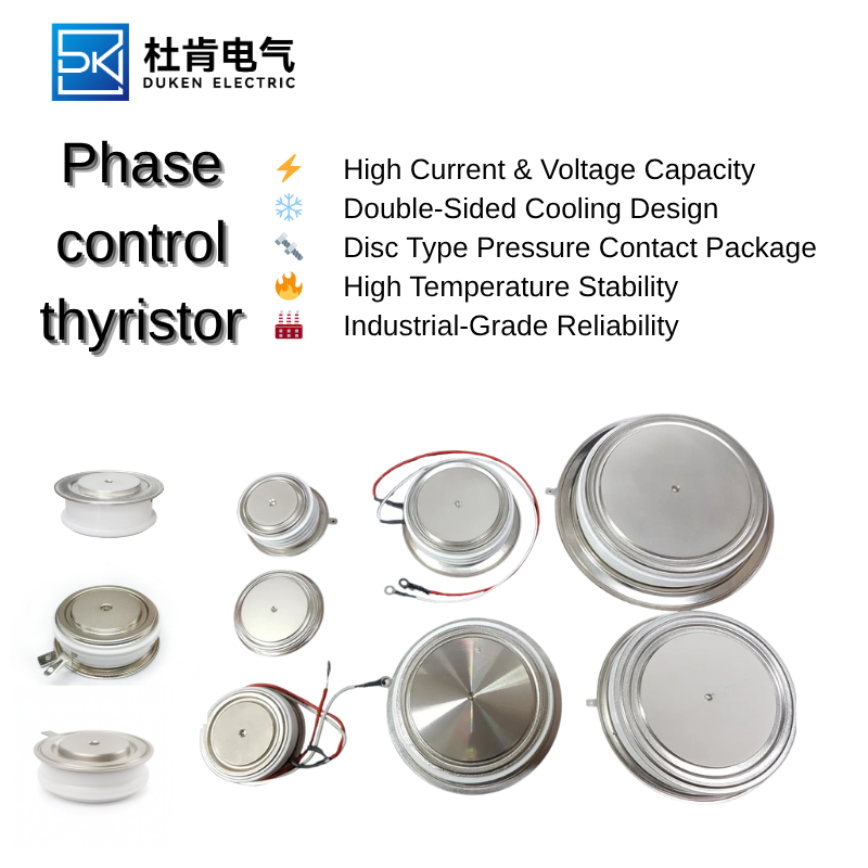
The package construction has a direct effect on heat dissipation and mechanical reliability. Disc-type thyristors are widely used in high-current applications because they provide double-sided cooling and strong pressure contact when installed correctly. The Aluminium housing disc package supports robust thermal spreading, mechanical protection, and practical integration into power stacks.
A high surge current rating Aluminium housing disc package 1400A phase control thyristor is suitable for applications where the device may experience fault currents or starting transients. However, surge capability should always be coordinated with fuse I²t, protection timing, and expected fault energy. The device must survive until the protection system clears the fault, and the protection system must clear the fault before the thyristor exceeds its safe limits.
Thermal design is equally critical. Engineers should calculate total loss, thermal resistance from junction to case, case to heatsink, and heatsink to ambient. Proper clamping pressure, clean contact surfaces, suitable thermal interface materials, and symmetric cooling are essential. A high-current thyristor may fail prematurely if it is mounted with uneven pressure or poor heat transfer, even when its electrical rating appears adequate.
5. Evaluate gate requirements and application compatibility
A phase control thyristor must turn on reliably at the required firing angle. Gate trigger current, gate trigger voltage, gate pulse width, and gate power must be compatible with the control board or driver transformer. In noisy industrial systems, weak gate pulses can cause misfiring, delayed conduction, or partial turn-on stress.
The device should also be checked for critical dv/dt and di/dt performance. High dv/dt can cause unwanted turn-on, while excessive di/dt during turn-on can create localized heating before the whole junction conducts. Proper gate drive design, series inductance control, and snubber selection help protect the device.
When comparing options, the datasheet KP1400A‑6500V low leakage current 1400A phase control thyristor should be reviewed alongside system-level requirements such as cooling method, overload profile, protection coordination, and maintenance environment. The best device is not always the one with the highest single rating; it is the one whose electrical, thermal, mechanical, and control characteristics match the actual operating conditions.
A high surge current rating Aluminium housing disc package 1400A phase control thyristor provides a strong foundation for high-power industrial design, but reliable performance depends on correct derating, accurate thermal modeling, careful mounting, and suitable protection. By treating the thyristor as part of a complete power conversion system, engineers can choose a component that delivers stable control, high blocking reliability, and long service life.